Product Documentation
- LED Products
- Arduino Products
- Audio Products
- Timekeeping Products
- Power Products
- Wire Products
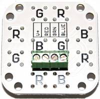
 The Satellite Module 001 is an 10 LED array of five-chip 100mA wide-angle (140 degree) red, green, and blue LEDs. The percieved output power of the red channel is a little less than the blue and green channels, so there are 4 red, 3 blue, and 3 green LEDs. Each LED supplies ~35,000 mcd over a 140 degree viewing angle. Combine with the ShiftBar to create a string of super-bright clusters. These are as bright as 15 ShiftBrites on the blue and green, and 20 ShiftBrites on the red channel!
Each channel of the Satellite Module requires 9 to 10 VDC at 100mA. There are no current control resistors, you can add your own or use this with a ShiftBar, which has current control. When using a ShiftBar, the potentiometer should be set around 75%.

| Function: | High-brightness RGB LED Array |
|---|---|
| Works with: | ShiftBar, current controlled sink drivers |
| Power Supply: | 8.4V on red, 10.2V on blue and green |
| Current: | 100mA per channel, 300mA total |
| Output: | Approx. 430,000mcd total |
| Viewing Angle: | 140 degrees |
| PCB Size: | 1.55“ by 1.55” |
![]() Important: The Satellite Module 001 does not have current control resistors installed. It is intended to be used with a current controlled sink driver, such as the ShiftBar.
Important: The Satellite Module 001 does not have current control resistors installed. It is intended to be used with a current controlled sink driver, such as the ShiftBar.
If a current controlled source is not available, then resistors will need to be added to the external circuit. To drive the Satellite Module 001 from 12V, series resistors of 18 ohms would be required on the blue and green channels, while a series resistor of 36 ohms would be needed on the red channel. All resistors should be rated 1/2 watt.
Of course, the easiest way to use the Satellite Module 001 is to use a ShiftBar to drive it. The ShiftBar controls up to 150mA on three channels with 10-bit PWM, and easily connects to the Satellite Module 001 using four wires.
