Product Documentation
- LED Products
- Arduino Products
- Audio Products
- Timekeeping Products
- Power Products
- Wire Products
 This documentation is for the Shades Audio Sensor V2, which is the production version. A small number of an earlier design were previously sold, the documentation can be found here: Shades Audio Sensor (OLD VERSION)
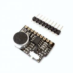
The Shades Audio Sensor is a small circuit board that can be soldered to either the LED Matrix Shades or the RGB Shades. The built-in microphone picks up ambient sound and music, which is amplified and fed into an MSGEQ7 seven-band frequency analysis chip. The MSGEQ7 provides analog voltages to the RGB Shades or LED Matrix Shades corresponding to the sound levels present in each of the seven frequency bands. This enables the microcontroller on the Shades to analyze sounds and display various types of audio visualizations. A sensitivity switch allows operation with normal music levels or very loud concert levels.
| Technical Specifications | |
|---|---|
| Supply Voltage | 3.3V to 5.5V |
| Microphone Gain | -44 dB |
| Preamp Gain | +13 or +28 dB |
| MSGEQ7 Gain | +22 dB |
| Bandpass Filters | 63Hz, 160Hz, 400Hz, 1.0kHz, 2.5kHz, 6.25kHz, 16kHz |
| SPL Range | 70 dB SPL to 110 dB SPL (approximate) |
| Input Signal | 3.3V or 5V logic reset and strobe signals |
| Output Signal | 0 to VCC analog level |
| Dimensions | 23x17x7mm |
| Connector | 1×9 2.54mm (0.1“) header |
If you're using the Shades Audio Sensor with the RGB Shades, we recommend using our custom 24AWG Power-only USB Cable to connect power to the RGB Shades from a USB battery pack. The RGB Shades are a fairly high-power device, and draw large pulses of current to power the LEDs. We included a very thin USB cable for ease of wearability with RGB Shades shipped before January 12th, 2016. Normally, this cable is not problematic, but the analog circuitry of the Shades Audio Sensor is sensitive to noise on the power rails. The custom cable greatly reduces power supply noise. It is only a power cable; while we generally don't like power-only cables, we needed to make a compromise in order to supply enough current while keeping the cable thin enough to wear comfortably.

On the Shades Audio Sensor V2, there is a small switch to select high and low audio sensitivity (marked H and L). Use low sensitivity in very loud areas, and high sensitivity with normal audio levels.

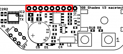
A 1×9 header is provided, but you will only need 1×8 as the RGB Shades expansion header only has 8 pins. Clip off the extra pin on the header, and solder the header to the Audio Sensor as indicated by the red box in the image below. Solder the header to the RGB Shades controller board as shown.

The whole 1×9 header is needed, but the LED Matrix Shades expansion header has 10 pins. The Shades Audio Sensor must be in the rightmost position on the LED Matrix Shades as shown below.

Select the matching code for your version of Shades and try downloading it to test the Shades Audio Sensor. If you are not using the Shades Audio Sensor with Shades, you can simply use the code below as a guideline for your own application.
Audio-reactive code for the RGB Shades is available on Github. You can browse the code here: https://github.com/macetech/RGBShadesAudio
To program the RGB Shades with the audio-reactive code, follow the steps below:
Audio-reactive code for the LED Matrix Shades is available on Github. You can browse the code here: https://github.com/macetech/LEDMatrixShadesAudio
To program the LED Matrix Shades with the audio-reactive code, follow the steps below:
Here is a link to the PCB and schematic files: Shades Audio Sensor OSHW Files