Visit our store!

Product Documentation
- LED Products
- Arduino Products
- Audio Products
- Timekeeping Products
- Power Products
- Wire Products
Visit our store!
 RGB Shades are a wearable LED matrix shaped like slotted sunglasses. The current version was developed as the result of a Kickstarter campaign and are currently available for sale on macetech.com. They are made from FR4 PCB material and M3 hardware. An Arduino-compatible microcontroller can generate a wide variety of colorful pixel patterns. The RGB Shades are powered and programmed through a USB connector; a rechargeable USB battery pack can be used for portability. New patterns can be developed and uploaded to the RGB Shades from any computer with a USB port.
The RGB Shades are intended for entertainment purposes only. They do not provide any eye protection, either from sunlight or flying objects. Vision is partially limited while wearing these, and they should never be used while driving or operating any other machinery that could potentially cause harm to yourself or others. Please take extra care while walking, and remove the glasses if there is a risk of tripping or bumping into objects or people. In most cases, vision is more than adequate to navigate a crowded room without any problems, but removing the RGB Shades for a few seconds is much less embarrassing than falling down.
Since the RGB Shades are made from exposed circuit boards, they are FRAGILE and should be treated with care. Do not bend, twist, hit, or scratch the circuit boards. A small scratch from a metal object could easily prevent one or all of the LEDs from working. Keep away from liquids; if splashed, turn off immediately and let dry before testing again. Keep away from any conductive objects; placing them in a pocket with keys and coins is likely to result in damage. Don't drop the glasses on a hard surface. In summary, the RGB Shades are more fragile than your cell phone, so please treat them accordingly. Damage to the PCB itself (scratches or excessive bending) cannot be repaired.
The above is what COULD happen, but in practice they are fairly durable and will likely survive accidental contact with dirt and liquids. The main cause of damage would be impact with sharp objects or actual destruction of the circuit boards.
We expect RGB Shades to be trouble-free under the right conditions, and with adequate care. However, like any other complex electronic device, failures are possible. While we can repair the RGB Shades, some problems are not actually failures, but can be resolved in other ways. The guide below will help you determine whether hardware failure has actually occurred.
| Symptom | Resolution |
|---|---|
| Won't turn on | Make sure the power supply is charged, switched on, and is rated for at least 1000mA. |
| Make sure cable from controller to LED panel is securely connected | |
| Verify USB cable is good; test with a different cable | |
| Only show blue | Make sure power supply is rated for at least 1000mA |
| Make sure cable from controller to LED panel is securely connected | |
| Use programming instructions below to reload firmware | |
| Not recognized by computer USB port | You may be using a power-only cable shipped with the RGB Shades. Try a normal USB mini-B cable. |
| Some computers have trouble recognizing USB over the very thin cable shipped with RGB Shades. Try a normal USB mini-B cable. | |
| Make sure newest FTDI drivers are installed | |
| Only some of the LEDs light up | Use programming instructions below to reload firmware |
| Nothing above helps | Contact us at sales@macetech.com |
| Some LEDs stay on | |
| Some LEDs stay off | |
| Parts missing |
The RGB Shades are under active development. The hardware files are distributed as Open Source Hardware (OSHW) under the CERN OHL v1.2 license. The firmware files are distributed open-source under the MIT software license. The firmware and hardware source can be downloaded here:
RGB Shades code on GitHub: https://github.com/macetech/RGBShades
RGB Shades hardware files: https://www.macetech.com/RGBShadesV3.zip
RGB Shades are currently delivered as a DIY kit for assembly. The following YouTube video explains how to assemble the RGB Shades. We've also added a video showing how to add heat shrink tubing to the earpieces to make them more comfortable.
| Technical Specifications | |
|---|---|
| Display Area | 68 WS2812B RGB LEDs, 16×5 logical matrix |
| Display Bitdepth | 256-level PWM brightness control of each color on each LED |
| Display Brightness | Global brightness control of full array (up to 256 levels) |
| Power Supply | 5V 1A (through mini-USB connector) |
| Battery Life | ~3 hours on 2000mAh battery pack, variable |
| On-board Processor | ATmega328P at 16MHz, Arduino-compatible bootloader |
| Communications | Built-in FTDI USB-RS232 converter |
| Auxiliary Interface | I/O pins available for hacking |
 The RGB Shades power switch will apply 5V power to the microcontroller and LED array. When the switch is in the ON position (pushed up and back), the RGB Shades will draw 5V power from the mini-USB connector. When the switch is in the OFF position (pushed down and forward), the RGB Shades will not draw any power. Only regulated 5V power should be connected to the USB connector or the 5V input pads.
 Control of the RGB Shades is possible by pressing the two small pushbuttons labeled 1 and 2. These buttons are read by software in the microcontroller, so their functions can be completely reprogrammed in code. However, our default software uses the buttons in the following way:
Button 1 short press / click: Select the next animation available in the list of animations.
Button 1 long press / hold: If the button is held for more than one second, it will toggle between auto cycle and manual cycle modes. Auto cycle mode will automatically switch to the next pattern in the list after 15 seconds. Manual cycle mode will stay on the current pattern unless Button 1 is clicked to select another pattern. When auto cycle mode is activated, the RGB Shades will blink blue once. When manual cycle mode is activated, the RGB Shades will blink red twice.
Button 2 short press / click: Increases the overall brightness level. When maximum brightness is reached, it will cycle to the lowest brightness.
Button 2 long press / hold: If the button is held for more than one second, it will set the brightness to the default startup value (midrange).
Since the RGB Shades are powered using 5V, a range of power supply configurations is possible. The most useful power supply is a rechargeable USB battery pack capable of at least 1000mA output. They are available in a wide range of capacities, but 2000-3000mAh is a good compromise between runtime and size. Here's a high quality one we've tested with the RGB Shades: Jackery Mini Premium 3350mAh
Power requirements vary significantly depending on the currently displayed pattern and the overall brightness setting. Our default software sets the initial overall brightness between 50 and 70 (out of 255). This is usually bright enough for most environments, and can actually be far too bright for a dark room. We don't recommend modifying the code to the maximum brightness, as the LEDs will begin to heat up and it will draw more current than most USB battery packs can provide.
When connecting the RGB Shades to a computer for programming, it's also best not to set the brightness too high. Computer USB ports vary widely in the amount of current output possible, so it's best not to ask for more than 500mA. If you're having trouble uploading code to the RGB Shades, try setting them to minimum brightness first.

This cable is included with kits packed after January 12th, 2016. It is a thin power-only USB cable, sacrificing the data wires in order to increase the power conductors to 24AWG (much thicker than usual USB cables). The extra power handling capability improves performance with the Shades Audio Sensor by reducing the amount of power supply noise due to voltage drop in the cable. In kits that include this cable, we also supply a short data-capable USB cable for reprogramming the RGB Shades.

This cable was included with kits packed before January 12th, 2016. It is a very thin USB cable, much easier to wear than a typical USB cable. The conductors inside are very thin, therefore on some computers it may not be possible to program the RGB Shades using this cable due to voltage drop. If programming difficulties are encountered, we recommend trying a different, normal-sized USB cable. This cable (again due to the voltage drop) also generates some extra power supply noise with the Shades Audio Sensor, which is why we switched to the power-only cable above.
The Arduino IDE can be used to edit and download firmware to the RGB Shades. It is not just used for the RGB Shades; in fact it is used for many different types of hardware from different vendors (small controller boards such as the Arduino Uno). Since it is free open-source software and works on Windows, OSX, and Linux, we have chosen it as a convenient way to share and modify the firmware that controls the RGB Shades.
Many of our customers may already have the Arduino IDE installed. If you don't have it:
We recommend upgrading to the latest Arduino IDE if you're currently using 1.5 or older.
The RGB Shades code uses the FastLED library. Install it using the following process:
The RGB Shades require fairly complex code in order to manage the basic functionality, so it's a good idea to start with our example code. We are developing the code on Github (https://github.com/macetech/RGBShades) and you can add it to your Arduino installation using the following process:
Next, we need to make sure the RGB Shades are recognized in the Arduino IDE:
A list of ports should appear. On Windows computers it will appear as “COMx” where “x” is some number. Your computer may already have other serial ports, so the easiest way to find the LED Shades is to check the list with the RGB Shades unplugged from the computer, and then check again for a new COM port with the glasses plugged in. Don't select any unknown ports or anything marked as Bluetooth; none of that is attached to the RGB Shades.
If the steps above don't show the RGB Shades serial port, you may need to install the FTDI driver. The RGB Shades use an integrated USB-to-serial converter chip (FT230X). This will allow your glasses to appear as a USB serial port when plugged into your computer, which is required for downloading new firmware to the glasses. Many computers already have FTDI drivers, but the FT230X chip is relatively new and may require a driver update. We recommend that before you begin, you should visit the following website, locate the appropriate driver for your computer's operating system, and install it: https://www.ftdichip.com/Drivers/VCP.htm
Later versions of RGB Shades no longer use the FTDI USB-serial converter. If the steps above don't show the RGB Shades serial port, you may need to install the Silabs driver. The RGB Shades use an integrated USB-to-serial converter chip (CP2104). This will allow your glasses to appear as a USB serial port when plugged into your computer, which is required for downloading new firmware to the glasses. Many computers already have the right drivers, but your computer may require a driver update. We recommend that before you begin, you should visit the following website, locate the appropriate driver for your computer's operating system, and install it: https://www.silabs.com/products/development-tools/software/usb-to-uart-bridge-vcp-drivers
In the Arduino IDE main toolbar, click on the Tools menu and hover over the Board option. A list of possible board types will appear; only one will work correctly with the RGB Shades.
If your RGB Shades were purchased before July 2015:
This version has the standard Arduino bootloader. R9 and R10 near the control buttons will be present.
Select the “Arduino Pro or Pro Mini” option. Then, go back into the Tools menu and find the Processor option and select “ATmega328 (5V, 16MHz)”.
If your RGB Shades were purchased after July 2015:
This version has the Optiboot bootloader. R9 and 10 near the control buttons will be missing.
Select the “Arduino Mini” option. Then, go back into the Tools menu and find the Processor option and select “ATmega328”.
The above steps should now allow you to program the RGB Shades. Try it out using the following steps:
The code should compile and the yellow LEDs on the side of the RGB Shades should blink for a few seconds. When the upload is complete, you should be able to see your custom messages displayed on the RGB Shades.
You can easily edit the code to display other patterns. It does require a level of programming knowledge, but we are working on more patterns you can simply upload without writing code. We are also working on easier ways to create and upload patterns with a graphical tool instead of code.
The Codebender service was shut down, please use the Arduino IDE programming method described below. We'll update with another easy programming method if we find one!

The controller board provides access to several digital and analog pins for adding your own circuitry to the RGB Shades. The I/O header is an 8×1 0.1“ connector layout, with access to 5V power, ground, analog pins 3, 4, and 5, and digital pins 6, 7, and 8. These pins can be controlled using standard I/O pin access commands in the Arduino IDE.
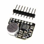
The Shades Audio Sensor can be soldered to the RGB Shades, allowing them to analyze nearby sound and music. The module integrates with the RGB Shades auxiliary I/O pins and includes a built-in microphone and MSGEQ7 7-band analysis chip. With the right code, the RGB Shades can generate sound-reactive patterns that dance in time with the music.
 For more advanced hardware hacking, we also provide a “hacker panel” which is simply a replacement earpiece with no electronic parts, and a small prototyping area. It provide direct access to the LED control pins, and the 0.1” headers are spaced a maximum of 0.6“ apart making it possible to attach a wide range of microcontroller modules.